diff options
Diffstat (limited to 'keyboards/converter/ibm_5291/readme.md')
| -rw-r--r-- | keyboards/converter/ibm_5291/readme.md | 70 |
1 files changed, 70 insertions, 0 deletions
diff --git a/keyboards/converter/ibm_5291/readme.md b/keyboards/converter/ibm_5291/readme.md new file mode 100644 index 000000000..06ae2e994 --- /dev/null +++ b/keyboards/converter/ibm_5291/readme.md @@ -0,0 +1,70 @@ +# IBM 5291 keyboard converter + + + +A converter for the eponymous keyboard. + +Keyboard Maintainer: [Listofoptions](https://github.com/listofoptions) +Hardware Supported: IBM 5291, Teensy 2.0 + +Make example for this keyboard (after setting up your build environment): + + make converter/ibm_5291:default + +See the [build environment setup](https://docs.qmk.fm/#/getting_started_build_tools) and the [make instructions](https://docs.qmk.fm/#/getting_started_make_guide) for more information. Brand new to QMK? Start with our [Complete Newbs Guide](https://docs.qmk.fm/#/newbs). + + +the pinout is as follows: + +IBM−5291−Cable to Pinhead−14 + +| pin | description +----|------------------------ +1 | GND +2 | NC +3 | GND +4 | GN) +5 | +5V +6 | D0 +7 | D1 +8 | D2 +9 | D3 +10| D4 +11| D5 +12| D6 +13| Strobe +14| Out + +the pins on this connector are organized 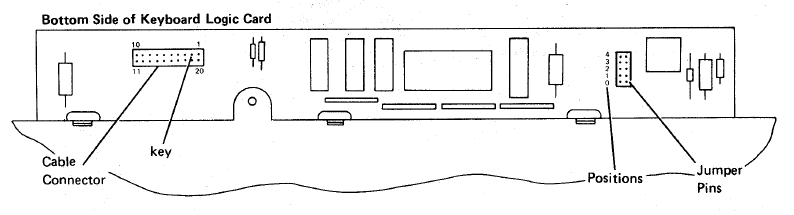 + +IBM−5291−2 Cable with DB15M connector + +| pin | description +----|------------- +|1,2,3 | GND +|4 | +5V +|5 | D0 +|6 | D1 +|7 | D2 +|8 | D3 +|9 | D4 +|10 | D5 +|11 | D6 +|12 | Strobe +|13 | Out +|14 | PE +|15 | NC + +the above connector is actually numbered so it should be easier to determine +where the needed connections are. + +to connect to the teensy, the following are pins are needed (if you should choose not set your own): +* PB0 -> PB6 are connected to D0 -> D6 +* +5V is connected to the corresponding teensy pin +* gnd is as well, only one of the gnd pins needs to be connected though. +* strobe is connected to pin PD1 +* data is connected to PD0 +* PE does not need to be connected to anything, but it could also be connected to gnd + +sources: + http://www.retrocomputing.eu/documents/5291_MaintenanceLibrary.pdf |