1
2
3
4
5
6
7
8
9
10
11
12
13
14
15
16
17
18
19
20
21
22
23
24
25
26
27
28
29
30
31
32
33
34
35
36
37
38
39
40
41
42
43
44
45
46
47
48
49
50
51
52
53
54
55
56
57
58
59
60
61
62
63
64
65
66
67
68
69
70
71
72
73
74
75
76
77
78
79
80
81
82
83
84
85
86
87
88
89
90
91
92
93
94
95
96
97
98
99
100
101
102
103
104
105
106
107
108
109
110
111
112
113
114
115
116
117
118
119
120
121
122
123
124
125
126
127
128
129
130
131
132
133
134
135
136
|
# XD84
Development docs covering the following:
- Kimera core
- RGB
- Backlight
- Light Through Cat
## Kimera core
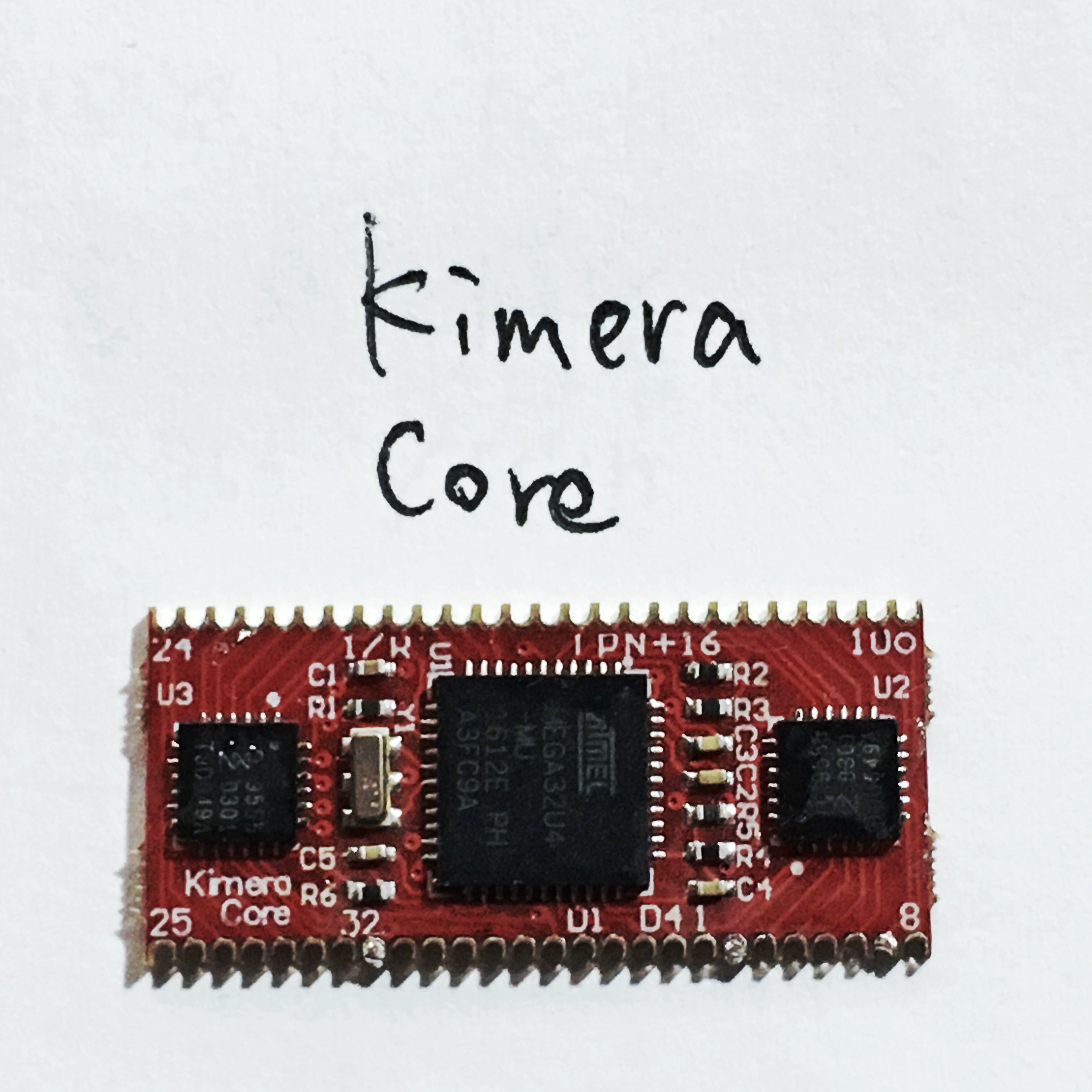
What little available info that was available for the qmk port
- atmega32u4 16Mhz
- board seems to have a 6Mhz crystal
- 2x PCA9555 I2C IO expander
Links:
- [Schematic, BOM, Gerbers](/kairyu/kimera/blob/master/kimera_core)
- [Original firmware](https://github.com/kairyu/tmk_keyboard_custom/tree/master/keyboard/kimera)
```c
/*
Kimera_core_v1.0 Components
U1 (atmega32u4)
,----------------.
TX --| TX0(PD3) RAW |--
RX --| RX1(PD2) GND |--
--| GND RESET |-- RST
--| GND VCC |--
SDA --| 2(PD1) (PF4)A3 |--
SCL --| 3(PD0) (PF5)A2 |--
(INT) --| 4(PD4) (PF6)A1 |--
--| 5(PC6) (PF7)A0 |--
--| 6(PD7) (PB1)15 |-- SCK
LED2 --| 7(PE6) (PB3)14 |-- MISO
LED1 --| 8(PB4) (PB2)16 |-- MOSI
LED3 --| 9(PB5) (PB6)10 |-- LED4
`----------------'
IC1 (PCA9555) IC2 (PCA9555)
,----------. ,----------.
SDA --| SDA P00 |-- P1 SDA --| SDA P00 |-- P17
SCL --| SCL P01 |-- P2 SCL --| SCL P01 |-- P18
INT --| INT P02 |-- P3 INT --| INT P02 |-- P19
| P03 |-- P4 | P03 |-- P20
GND --| A0 P04 |-- P5 VCC --| A0 P04 |-- P21
SJ1 --| A1 P05 |-- P6 SJ1 --| A1 P05 |-- P22
SJ2 --| A2 P06 |-- P7 SJ2 --| A2 P06 |-- P23
| P07 |-- P8 | P07 |-- P24
| | | |
| P10 |-- P9 | P10 |-- P25
| P11 |-- P10 | P11 |-- P26
| P12 |-- P11 | P12 |-- P27
| P13 |-- P12 | P13 |-- P28
| P14 |-- P13 | P14 |-- P29
| P15 |-- P14 | P15 |-- P30
| P16 |-- P15 | P16 |-- P31
| P17 |-- P16 | P17 |-- P32
`----------' `----------'
*/
```
### Bootloader
Default bootloader is `atmel-dfu`.
Reboot to bootloader via magnetic switch next to icsp header.
Flash using regular dfu methods.
### XD84 pin mappings
Taken from [kimera-config.json](https://github.com/kairyu/tkg/blob/master/keyboard/config/kimera-config.json)
"row_mapping": [ 1, 2, 3, 4, 5, 6 ],
"col_mapping": [ 17, 18, 19, 20, 21, 22, 23, 24, 25, 26, 27, 28, 29, 30, 31 ],
# RGB
- PIN C7
- Number of RGB LED 7
# Backlight
- PIN B6
# Light Through Cat
TODO - PWM C6
## Assumptions
### Pin/Port mappings
- All cols are on the same IC
- All rows are on the same IC and port
- Pins mapped sequentially
- Each port only does row or column not a mixture of both
- No need to have complex port config
-
| ROW index | Kimera Pin | PCA9555 |
| ----------|------------|-------------------|
| 0 | 1 | IC1 Port 0 pin 0 |
| 1 | 2 | IC1 Port 0 pin 1 |
| 2 | 3 | IC1 Port 0 pin 2 |
| 3 | 4 | IC1 Port 0 pin 3 |
| 4 | 5 | IC1 Port 0 pin 4 |
| 5 | 6 | IC1 Port 0 pin 5 |
- Safe enough to assume `row_index == pin`
| COL index | Kimera Pin | PCA9555 |
| ----------|------------|-------------------|
| 0 | 17 | IC2 Port 0 pin 0 |
| 1 | 18 | IC2 Port 0 pin 1 |
| 2 | 19 | IC2 Port 0 pin 2 |
| 3 | 20 | IC2 Port 0 pin 3 |
| 4 | 21 | IC2 Port 0 pin 4 |
| 5 | 22 | IC2 Port 0 pin 5 |
| 6 | 23 | IC2 Port 0 pin 6 |
| 7 | 24 | IC2 Port 0 pin 7 |
| 8 | 25 | IC2 Port 1 pin 0 |
| 9 | 26 | IC2 Port 1 pin 1 |
| 10 | 27 | IC2 Port 1 pin 2 |
| 11 | 28 | IC2 Port 1 pin 3 |
| 12 | 29 | IC2 Port 1 pin 4 |
| 13 | 30 | IC2 Port 1 pin 5 |
| 14 | 31 | IC2 Port 1 pin 6 |
- Safe enough to assume here col_index does not need to be converted to pin
- Reading both ports one after the other gives us the same sequential behavior
- maps to the usual practice of reading matrix columns
- while this technically gives 16 column reads, the 16th column can never be set so is safely ignored
## Notes
[pca9555 datasheet](https://www.ti.com/lit/ds/symlink/pca9555.pdf)
- Other Kimera based boards with non sequential pin mappings, pins mapped across ICs, or mixed row/col configs will need more complicated `pin -> i2c_addr,port,pin` logic as well as rather more complex pin functions.
## Return to stock firmware
Not tested but original firmware seems to be available in the [kairyu/tkg-firmware](https://github.com/kairyu/tkg-firmware/blob/master/kimera-core.hex) repo.
|